01
Choosing the Right Battery for the Duty
Battery selection starts with the load profile. A system supplying a modest current for several hours has different requirements from an engine-starting system delivering a short, high-current pulse. Mixed duties can combine continuous loads with switching, tripping or starting peaks. Select the cell range using its discharge-performance data, rather than nominal ampere-hour capacity alone.
02
Battery Sizing and System Voltage
A sizing study should consider the complete discharge sequence, minimum acceptable load voltage, cable voltage drop, operating temperature and required recharge time. Include continuous loads, intermittent loads and the order in which they operate. The selected battery must support the most demanding part of the duty, not simply the average current.
For series-connected cells, the string voltage is the sum of the individual cell voltages. Cell count must satisfy both the equipment’s minimum voltage during discharge and its maximum allowable voltage during charging. Increasing the number of cells to improve discharge performance also increases the charging voltage, so both limits need to be checked together.
03
Charging and Recovery After Discharge
Standby batteries commonly operate with a charger supporting the load and maintaining battery charge. Depending on the selected range, the system may use a single charging level or separate float and boost levels. The correct setting depends on the battery design, temperature, voltage limits of connected equipment and the required recovery time.
Charger selection must allow for the normal connected load as well as battery recharge demand. Check voltage range, current limit and the time available before another discharge. A higher charging voltage is not automatically suitable: it can increase water consumption and may exceed the equipment’s voltage limit. Use the approved NICA settings for the installed model.
04
Temperature and Operating Conditions
Ambient temperature affects available discharge performance, charging behaviour and maintenance requirements. Assess the lowest expected battery temperature when selecting capacity, particularly for high-current duties. High-temperature operation can increase water consumption and shorten topping-up intervals in vented cells.
State the normal, minimum and maximum temperatures for the actual installation. Do not assume that an operating-temperature limit guarantees full rated capacity at that temperature. Temperature correction factors and any charger compensation must come from the selected battery range’s data.
05
Installation, Rack Layout and Commissioning
Plan rack access around inspection, cable routing and safe replacement of individual cells. Confirm the approved arrangement, floor loading, clearances and protection of live connections before installation. Ventilation must suit the battery type and charging conditions; reduced water consumption does not remove the need to assess gas release.
Commissioning should be carried out by trained personnel using the approved installation instructions. Record the battery identity, cell count, polarity, connection checks, electrolyte condition where applicable, charger settings and initial measurements. The initial charge procedure depends on the condition in which the battery was supplied and how it was stored.
06
Inspection and Preventive Maintenance
Inspect the battery, charger and associated equipment as one system. Routine checks include cleanliness, signs of damage or leakage, electrolyte level where applicable, connection condition, charging voltage and abnormal temperature. Record observations consistently so changes can be identified over time.
Where topping-up is required, use the specified distilled or deionised water and follow the model’s level marks and instructions. Electrolyte density is not a reliable indication of nickel-cadmium battery state of charge. “Maintenance-free” typically refers to no water addition under specified operating conditions; it does not mean that inspection of the installation can be omitted.
07
Monitoring and Performance Assessment
Trending voltage, current, temperature and electrolyte level, where sensors are fitted, helps identify changes in operating conditions and supports maintenance planning. Review alarms against the battery’s normal behaviour and the manufacturer’s limits. An isolated voltage reading should not be treated as proof of available capacity.
Capacity assessment requires an approved test procedure with defined load, duration, end voltage and temperature conditions. Plan the test around site continuity requirements and retain the results with commissioning and maintenance records. Monitoring and periodic performance checks serve different purposes and should complement each other.
08
End-of-Life Collection and Recycling
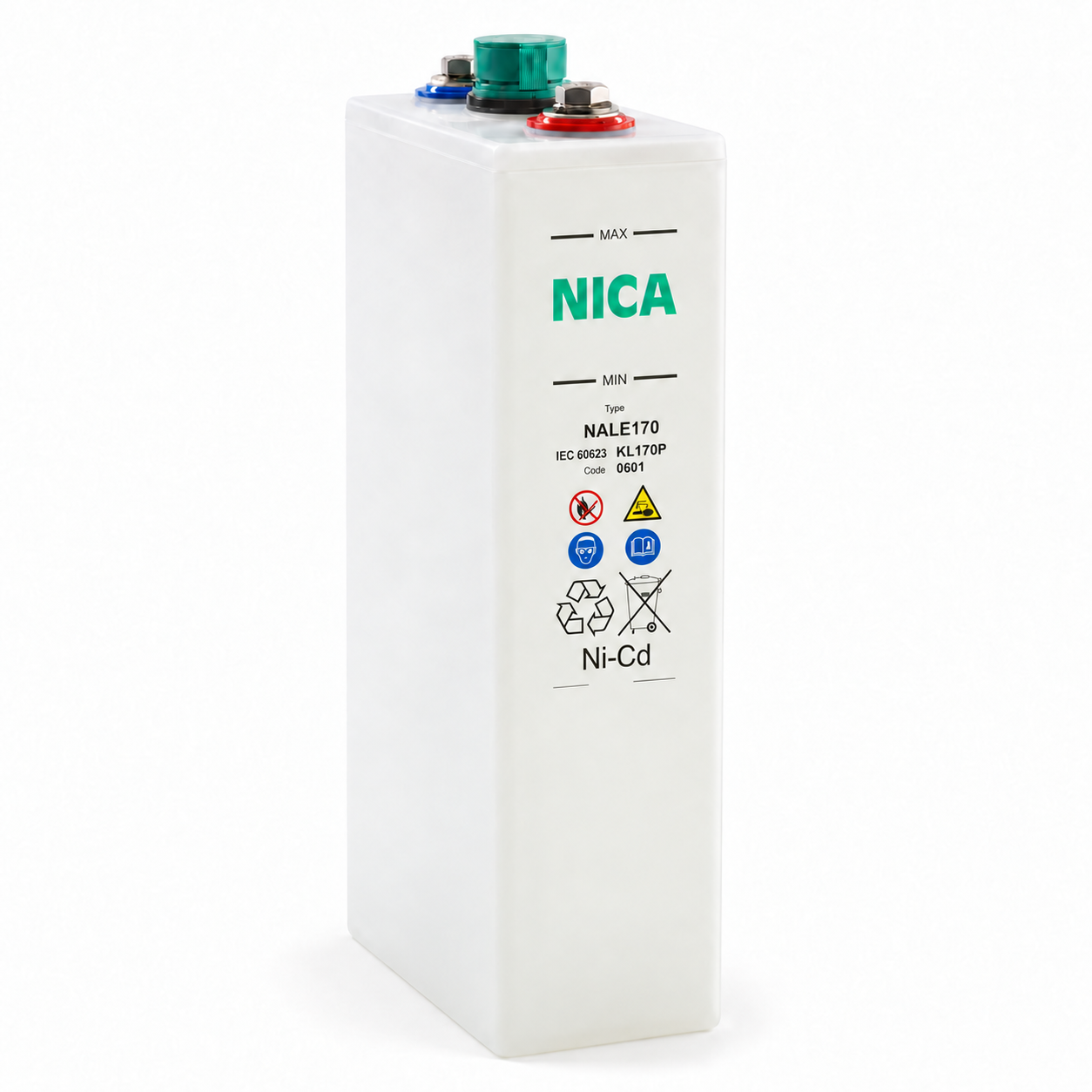
Nickel-cadmium batteries require controlled collection and specialist recycling. Keep retired batteries out of general waste and use authorised collection channels. Retain identification and collection records, and contact Nicad Power Pte Ltd for assistance with the appropriate return or disposal route.
09
Information for a Technical Review
Provide the load schedule, required back-up duration, minimum and maximum DC voltage, charger details, ambient temperatures, available installation space and any starting or switching peaks. Include the existing battery model and cell count for replacement projects. These details allow Nicad Power Pte Ltd to review the battery, charging system and physical arrangement together.
This guidance explains general nickel-cadmium battery principles. Final ratings, charging settings, installation requirements and maintenance procedures must follow the documentation supplied for the selected NICA battery.